MTR/SASSI implements a new Pipe element that allows piping systems to be included in the soil-structure interaction models. Because stiffness of pipe elements are dependent on the internal pressure and temperature of the pipes, they cannot be modeled using standard beam elements. The new pipe element procedure allows for proper modeling of straight and bend (elbow) pipe segments and supports the use of hangers, branch point and flexible supports.
Capabilities of New Pipe Element
- Straight Pipe elements are defined by two end nodes. Each node can have up to 6 DOF (3 translations and 3 rotations) and can transmit both axial and shear forces as well as bending moments.
- Bend (Elbow) Pipe elements are defined by two end nodes and one intermediate node defined by the center of curvature or tangent intersection point (TIP). Each of the three nodes can have up to 6 DOF (3 translations and 3 rotations) and can transmit both axial and shear forces as well as bending moments.
- Local coordinates of the pipe elements may be defined using one of four available methods including the default. This facilitates interpretation of pipe stress output.
- Pipe element material properties are temperature dependent and include Young’s modules, Poisson’s ratio and damping. The Piping temperatures are calculated internally by the program using the input nodal temperatures.
- Pipe element section properties include outside diameter, wall thickness, shape factor and weight per unit length.
- The geometry input data for piping system follows the general industry format which includes several different methods of inputting straight and bend pipe configuration. This facilitates data exchange with other piping programs.
- The effect of internal pressure and temperature on pipe stiffness are accounted for.
- The stress output includes axial and shear forces and bending moments defined in the local coordinates at pipe nodes.
Benchmark Test Problem
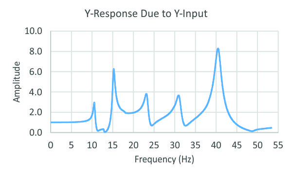
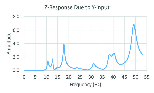
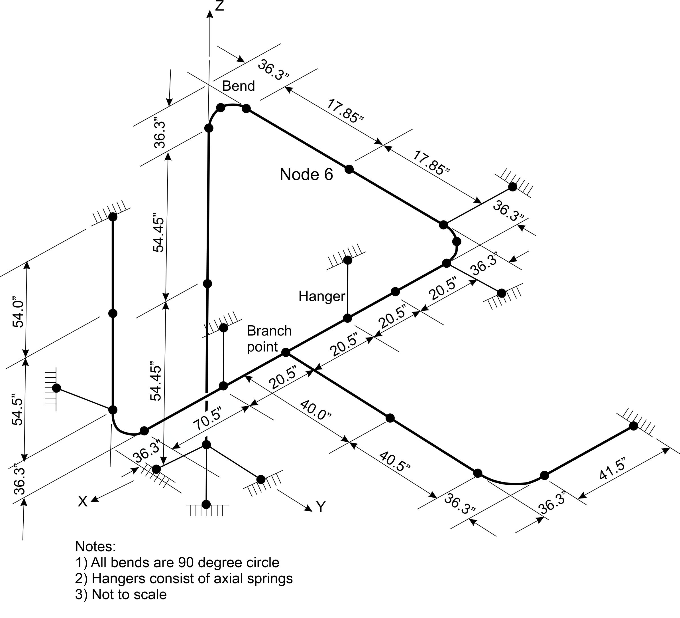
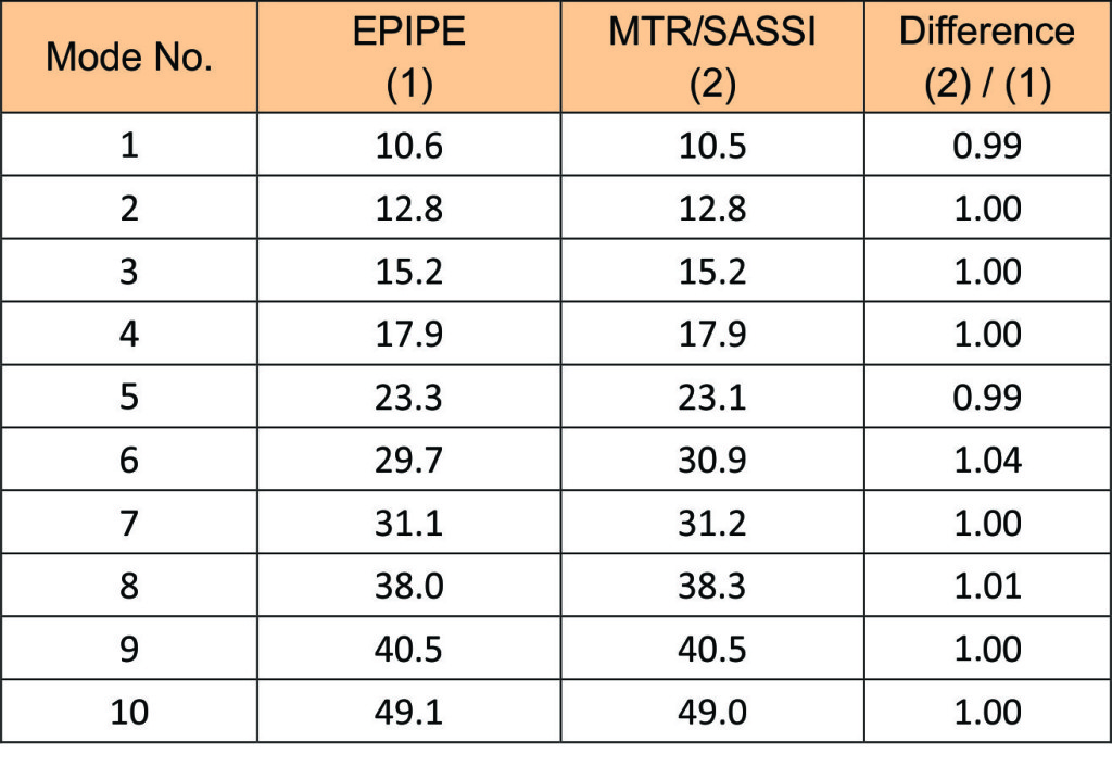
A benchmark test problem of a typical piping structure is used to evaluate the accuracy of the new pipe element implemented in MTR/SASSI. The configuration of the piping structure is shown below. It consists of straight pipe sections, several bends and a branch point. It also includes intermediate spring supports to simulate hangers and snubbers and a flexible anchor. The pipe properties are standard properties and include uniform internal pressure of 350 psi. The first 10 modal frequencies of the pipe structure calculated by EPIPE are shown in the table below. To extract similar frequencies from MTR/SASSI analysis, the model was subjected to unit amplitude harmonic motions at all the fixed support Nodes in the Y-direction. The results in terms of the computed transfer functions at Node 6 in the X-, Y- and Z-directions are shown below. To capture the above natural frequencies, the transfer function was calculated to a frequency of 53 Hz with a frequency resolution of 0.1 Hz. The peaks of transfer functions correspond to modes of the piping system. The frequencies of these modes are calculated and summarized in the table below. As seen from this table, there is excellent agreement between the piping system frequencies obtained from MTR/SASSI and those of EPIPE, which validates the dynamic stiffness formulation of Pipe element and solution in MTR/SASSI.
Configuration of Piping Structure
Comparison of Piping System Frequencies (Hz)
Transfer Functions at Node 6