MTR/SASSI implements a new Pile element for dynamic response analysis of structures supported on large pile group foundation.
Multiple structures on arbitrary foundations can be effectively analyzed taking into account the full dynamic structure-soil-pile interaction effects. The significant features of the new Pile element are listed and described below followed by a sample application to LNG tanks. For validation of the new Pile element, please go to Technical Notes posted on the web site.
Capabilities of New Pile Element
- Piles can have up to 6 DOF (3 translations and 3 rotations) per node and can transmit both axial and shear forces as well as bending moments.
- Pile section and material properties can vary along the pile as well as from pile to pile.
- Both end-bearing and friction piles can be analyzed.
- Both vertical and batter piles can be included in the pile group.
- Fixed-head condition can be imposed by restraining rotations at pile tops.
- Full kinematic and inertial effects on the pile group are considered in the analysis.
- Pile groups can be analyzed to derive the foundation dynamic stiffness and damping, which can then be linearized and input to a dynamic model of the structure in a two-step analysis or they can be integrated with the structure in a single SSI model and analyzed in one step in MTR/SASSI.
- Joint release and master/slave nodes can be imposed on the pile nodes.
- The effects of Soil nonlinearity due to the structural feedback can be modeled by including portion of the soil around the piles from ground surface to point of fixity of the piles in the SSI model. The properties of this soil block can be iterated on using the equivalent linear method.
- Liquefiable or soft soils within the foundation support zone can also be modeled as part of the structure. The properties of this zone can then be adjusted to reflect soil degradation.
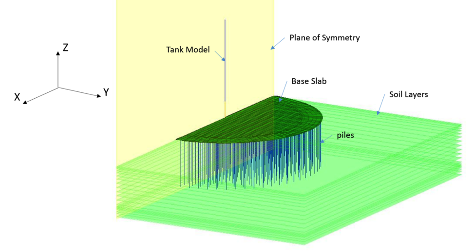
Typical LNG Tank Model on Large Pile Group Foundation

MTR/SASSI SSI Model
General Characteristics
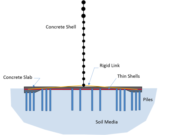
- Many of cryogenic LNG storage tanks consist of a concrete outer tank and a steel inner tank with tank diameters of 60-90m.
- The tanks are generally supported on improved ground at grade or on piles.
- Number of piles range from 300 to 2000 depending on pile type and diameter, and foundation footprint.
- Steel cylindrical tank is not anchored to the concrete slab to allow for expansion or contraction due to temperature.
- Annular space between the two tanks is insulated with perlite.
- Space between the bottom steel plate and concrete slab contains foam glass.
Tank Model
- Concrete outer tank and steel inner tank are modeled using lumped-mass stick models.
- Concrete base slab is modeled using plate/shell finite elements.
- Outer tank stick model is connected via rigid links to the perimeter of base slab for proper transfer the overturning moment.
- Mass of non-structural materials (perlite, steel liner, foam glass, steel plates, etc.) are distributed along the wall height.
- Mass of insulating material is added to that of base slab.
- Hydrodynamic effects are modeled using convective and impulsive mass computed based on Housner’s method and incorporated at appropriate elevations into the model.
Foundation Model
- Piles are modeled using new Pile elements connected at the top to the base slab. The nodes on the pile are defined as interaction nodes. Nodes on the base slab that are not connected to the piles are detached from the soil (i.e. defined as structural nodes).
Soil Model
- Soil media is modeled as horizontally layered system over uniform halfspace.
- Soil layer thicknesses must satisfy the passing frequency requirement.
li < Vis / 5 fpass)
where li is thickness of layer i, Vis is shear wave velocity of layer i and fpass is passing frequency.
- Nonlinear soil effects due to inertia effect of the structure may be modeled by incorporating a portion of soil mass around the piles from the bottom of base slab to a depth of about 5 pile diameters. The properties of the soil block can then be adjusted to reflect soil degradation.
- Liquefiable or soft soils within the foundation support zone can also be modeled as part of the structure. The properties of this zone can then be adjusted to reflect soil degradation.